
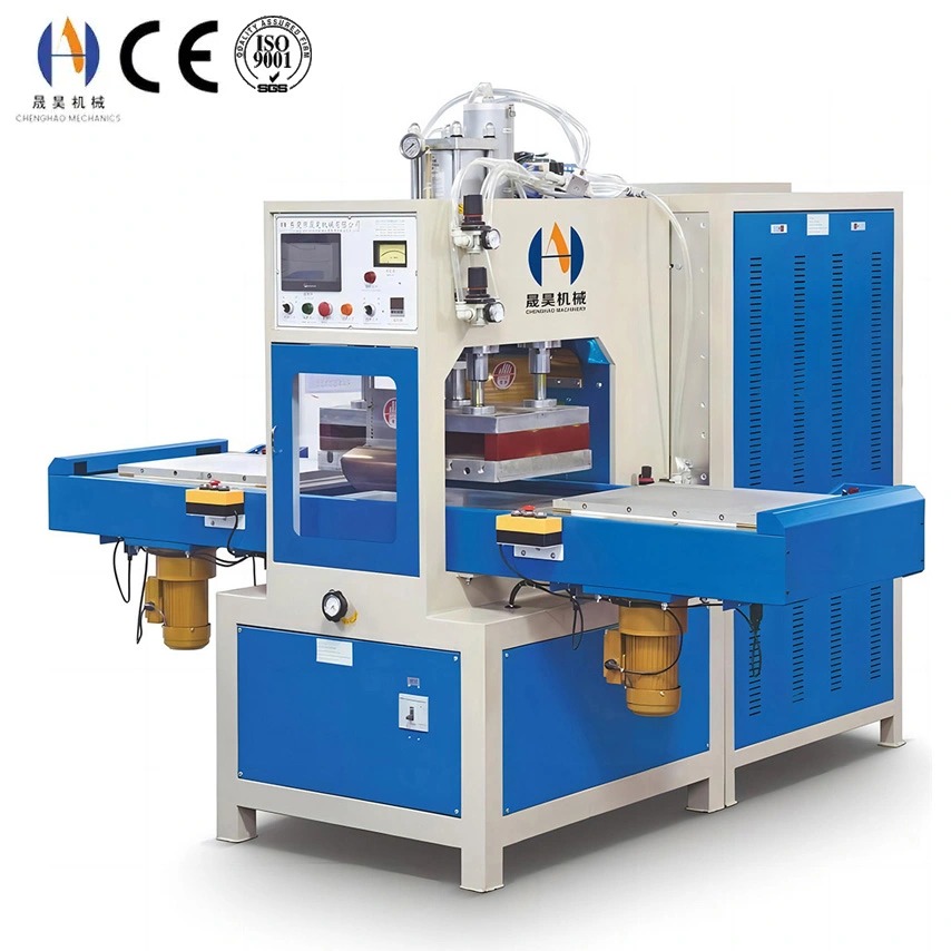
Weak high frequency welds are rarely caused by a single failed component, and this is why they are so often misdiagnosed. A seam that peels open might be blamed on a tired oscillator tube, when the real fault is an electrode that has stopped making even contact. It might be blamed on the operator, when the material has absorbed moisture overnight. Weak welds are the visible result of an imbalance somewhere in the four things HF welding depends on — power delivered, time at temperature, force applied, and the condition of the joint — and the troubleshooting job is to isolate which of those has moved. This guide sets out how to confirm that a weld is genuinely weak, how to trace it to a root cause, and how to correct the process permanently rather than chasing the symptom piece by piece.
First, Separate Weak From Under-Welded and Over-Welded
A weak weld is one that fails below the strength the application requires, and it fails in a characteristic way: the seam parts cleanly along the joint, often with little or no material transfer from one side to the other. This is different from an over-welded seam, which fails just beside the weld line because the material has been thinned and embrittled by too much power, pressure or time. Both are called "weak" on the shop floor, and they have opposite causes. Treating an over-welded seam by adding power makes it worse; treating an under-welded seam by reducing pressure does the same. The first step is therefore to look at where and how the joint fails.
| What You See on Failure | What It Usually Means | First Direction |
|---|---|---|
| Seam peels open with no tearing of the base material | Under-welded — the interface never reached fusion temperature | Increase power density or time; check contact |
| Failure just outside the weld line, material thinned and stiff | Over-welded — the joint is hot and thin, the surrounding film is the weak point | Reduce power, time or pressure; improve cooling |
| Strength varies around the same seam | Uneven field or pressure — a tooling, levelling or fixture problem rather than a setting | Inspect electrode flatness and parallelism |
| Strong the first shift, weak later in the run | A drifting variable — tube ageing, electrode heating, jig creep or ambient humidity | Log parameters over time; look for trend not average |
| Seam tears open, often with scorching or a pinhole | Arcing or burn-through beside a weak line — a contaminated surface or a sharp electrode edge | Clean material and dress electrode edges |
Test Before You Touch a Setting
It is common for a "weak weld" to be declared on the basis of a hand pull that felt easier than usual. That judgement is not repeatable, and adjusting the machine against it wastes time and usually pushes the process off a setting that was already correct. Before any parameter is changed, the loss of strength should be quantified, and the test should be one the plant can repeat on every batch. The method chosen depends on the product, but the principle is the same: apply a defined load to a defined specimen and compare against a documented minimum.
| Test | Best For | What It Reveals |
|---|---|---|
| Peel test | Flat seams, film and sheet, quick shop-floor check | Whether the interface fused and how consistent the fusion is along the seam |
| Tensile or lap-shear pull | Any seam where a number must be recorded | Load at failure, so a minimum can be set and trended against a before-and-after figure |
| Burst or pressure test | Inflatable or sealed products — bags, bladders, air cushions | Whether the whole seam holds as a system, and where the weakest segment sits |
| Visual and section cut | Confirming what the failure looks like internally | Weld depth, voids, contamination layers and whether the peel line is interface or base material |
Only once a repeatable number exists can a change be judged. The full set of variables that determine that number — frequency, power, time, pressure, electrode geometry and material grade — is examined in the guide to factors that affect high frequency welding strength, which is a useful companion to the diagnostic sequence below.
The Four Families of Root Cause
Almost every weak weld traces back to one of four families. Sorting the symptom into the right family first saves the most time, because it tells you whether to touch the generator, the press, the tooling or the material. The table below is the map; the sections that follow explain each family in detail.
| Family | Typical Signature | Where to Look First |
|---|---|---|
| Power and generator | Consistently weak everywhere, worse on thick or large parts | Tuning, tube condition, power density for the weld area |
| Pressure, time and cooling | Weak or thinned seams, sensitivity to small setting changes | Force calibration, dwell and cooling under pressure |
| Tooling and electrode | Strength varies along the seam; some parts good, some poor | Electrode flatness, surface condition, edge radius, jig support |
| Material and preparation | Sudden change between batches or shifts; bubbles and voids | Moisture, contamination, plasticiser, additive level, storage |
Power and Generator Causes
When every part on a given tool comes out weak, and the weakness grows with the size or thickness of the part, the generator side deserves attention before anything else. The most common single cause is simply insufficient power density — the watts available divided by the weld area. A tool that works on a small label can be starved on a large panel, and the seam then never reaches fusion temperature in the time allowed.
Insufficient Power Density
If the weld area has grown since the tool was specified, the generator may be at its limit. The symptom is a uniformly weak seam that cannot be fixed by extending dwell time, because the material is being heated too slowly to fuse before it cools.
Oscillator Tube Ageing
Output falls gradually as the high frequency electron tube nears end of life. Because the decline is slow, the first sign is usually a seam that needs more time than it used to, followed by one that stays weak however the timer is set.
Detuning
A change in tooling, cable routing or load capacitance can pull the circuit off resonance, so power is reflected rather than delivered. The tuning indicator or plate current will show it before the seam does, which is why routine tuning checks belong in the maintenance schedule.
Frequency Drift
A generator running away from its design frequency couples unevenly into the material. Where the drift is significant, seam strength falls even though indicated power looks normal, because the energy is being applied less efficiently.
Pressure, Time and Cooling Causes
The press side produces weak welds in both directions, which is what makes it a common source of confusion. Too little pressure and the two surfaces never make the intimate contact required for the field to bridge the interface, so the seam is weak while the machine's indicators look perfectly healthy. Too much pressure and the softened material is squeezed out of the joint, thinning the seam and leaving the surrounding film to fail first.
| Cause | Signature | Correction |
|---|---|---|
| Pressure too low | Weak everywhere, arcing more likely, no flash at the seam edge | Raise force until the seam just flashes; verify with a pressure gauge, not the regulator knob |
| Pressure too high | Excess flash, thinned seam, failure just outside the weld line | Reduce force; where geometry is complex, substitute a sprung or multi-stage clamp |
| Weld time too short | Weak seam that the operator compensates for by pressing twice | Extend dwell in small steps; a double-press is a symptom, never the fix |
| Cooling released early | Peel strength fine immediately, poor once the part relaxes | Hold pressure through cooling and open only after the seam has set |
| Force not square to the part | One side of the seam strong, the other weak | Level the platen and shim the jig so force is evenly distributed |
Tooling and Electrode Causes
When some parts from the same tool are strong and others weak, the problem is almost always mechanical rather than electrical. The electrode and mould set the current density and the force distribution, so any wear or fouling in them shows up directly as inconsistent strength. A build-up of plasticiser, release agent or degraded material on the electrode surface is one of the most under-diagnosed causes of a slowly weakening seam, because it changes contact without changing any setting on the machine.
| Condition | Effect on Strength |
|---|---|
| Electrode surface fouled or oxidised | Contact resistance rises, so the field spreads and density at the seam falls — the seam weakens gradually and the machine looks normal |
| Sharp or burred electrode edge | Concentrates the field and causes edge arcing or burn-through beside the weld, leaving a weak line where the arc has struck |
| Insufficient or uneven hold-down | Material lifts or shifts during welding, so part of the joint never closes; strength varies along the seam |
| Mould or platen out of flat | Force and field are concentrated where the faces touch first; the rest of the seam is starved and stays weak |
| Damaged jig or worn locating pins | Part position drifts, so the weld line does not align with the electrode and strength becomes erratic |
Because electrode condition matters this much, the geometry and surface specification deserve the same attention as the machine settings. A structured approach to edge radius, land width and relief is set out in the guide to designing electrodes for high frequency welding, and the consumables that keep them working at specification are covered under high frequency accessories.
Material and Preparation Causes
Material problems have a distinctive fingerprint: the seam is strong, then a new roll or a new day's production arrives and the seam is weak, with nothing changed on the machine. The single most frequent cause is moisture. PVC and TPU both absorb water, and that water converts to steam in the field, creating voids and a seam that looks welded but separates under load. A material that was left open overnight can behave completely differently from the same material taken straight from a sealed bag.
| Material Factor | Why It Weakens the Weld |
|---|---|
| Absorbed moisture | Turns to steam at weld temperature, forming voids and bubbles that break the bond area; strength drops sharply with only a small moisture increase |
| Surface contamination | Oil, dust, release agent or handling residue blocks the field from bridging the interface, creating a weak interface layer even when the weld looks complete |
| Plasticiser and additive variation | HF welding depends on the material's dielectric loss behaviour; too much plasticiser or the wrong filler changes how readily it heats, so a batch can weld poorly on unchanged settings |
| Thickness or laminate change | Thicker or differently laminated material needs more energy to reach fusion temperature; a gauge change silently shifts the whole process window |
| Thermal or UV ageing of the roll | Old stock can have altered surface properties, so performance varies between the start and end of a roll |
Material selection and conditioning interact strongly with the welding method, which is why the same film can weld well in one plant and poorly in another. The way different polymer families respond to the field is examined in how material properties affect the welding process.
A Step-by-Step Troubleshooting Sequence
Working through the families in a fixed order prevents the most common mistake in HF troubleshooting — changing several variables at once and then not knowing which one helped. The sequence below isolates one variable at a time, from the outside in.
Permanent Fixes and Prevention
Troubleshooting removes the immediate weakness; prevention keeps it from returning. Most plants that stop chasing weak welds do so by moving the effort upstream — controlling material, maintaining tooling and monitoring drift — rather than by becoming faster at adjusting settings after the event.
| Measure | What It Prevents |
|---|---|
| Sealed storage and a defined drying routine for hygroscopic material | The batch-to-batch weakness that appears after material has been left exposed |
| Incoming inspection of grade, gauge and additive level | The silent process shift caused by a supplier or formulation change |
| Scheduled electrode cleaning, edge dressing and flatness checks | The gradual strength decline from fouling and wear that no setting change can fix |
| Force calibration and timer verification on a fixed cycle | The slow drift of pressure and dwell that pushes a healthy process out of its window |
| Peel or pull test at defined intervals with recorded results | Weak welds reaching the next operation, and gives an early-warning trend before they do |
| Stored recipes locked against the part number | Reintroduction of a weak weld by an operator starting from the wrong baseline |
Where weak welds are frequent across many products, the wider production system is usually the place to look — the sequencing, tooling management and process control that reduce the conditions in which defects arise are discussed in reducing defects and downtime in HF welding production and in improving PVC welding quality.
Frequently Asked Questions
Trace Your Weak Welds to the Root Cause
Chenghao Machinery builds high frequency welding machines from 3 kW to 60 kW and supplies the electrodes, moulds and accessories that keep a seam at specification. Send us your material, tooling and current settings, and our engineers will help you isolate why the weld is weak and specify the correction.
Dongguan Shenghao Machinery Co., Ltd. (Chenghao Machinery) | sales11@chenghaointernational.com | +86 158 1765 5869
Dongguan, Guangdong, China